

MAKING THE MAP
To create a new real-life track we need first of all a clean and detailed map of that track, a map which is realistic as much as possible in the scale, in the radius of
the turns and in the length of the straights. Some pics of the track, better if aerial views, will be useful for a comparison with the map. Of course it’s impossible to
create a 100% realistic track but a good compromise will be enough. Nonetheless, Google Earth can help to create extremely detailed maps by. It is important that the
final image is a square (i.e. 2000 x 2000 pixels) and is saved as a .BMP being it the only supported format. In this example we'll make a huge map of the Albacete track.
Opened Google Earth we need to disable the terrain elevations to eliminate any distorsion. To do this, on the Tools menu, we need to uncheck the elevation checkbox.
Applying it we'll have the flat land. At this point it's important to allign the main straight of the track to the horizontal axis, trying to find the best result possible.
The program borders will be an excellent ruler. This zoom must never be changed during the process so it's better to store the coordinates by pinning the position.
Google Earth can create screenshots of the visible terrain and we can paste them next to each other on a bitmap as if we are assembling a puzzle. Then, open a new bitmap
sheet, giving it a reasonable big size, in example 4000 pixels on both width and height. Once ready we can start copying and pasting one at time these images. As the borders
of these images have to match perfectly, we may want to chose everytime particular details where to anchor each part.
Once done we need to determinate an exact dimension between two points. This will be used inside the track editor when it comes to find quickly the best scale possible to
resize the map. It will help to spot faster the real track length. For this task, we can use the ruler tool of Google Earth, making sure this distance is long enough to
balance eventual aproximations. In example let's try to measure the length of the main straight. Of course, we will annotate the start, the end and the lenght of the
distance we just measured, marking their exact positions on the bitmap to be easily found later. Here below is a miniature of the mig map assembled.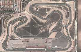
HOW TO START With the Gp3 Track Editor we can create brand-new tracks starting anyway from the original ones stored in the ‘circuits’ folder of the game. To simplify the editing, it would be good to choose a track that matches our needs. First we need to choose a slot of the 16 available with a minimum length necessary to load our own without magicdata. Indeed a limit of Gp3, if GpxPatch and/or magicdata are not used, is the length of the track. So if our track is around 4.0 Km, which are 820 units (where 1 unit is around 4,87 meters), we should consider this list of lengths. slot 1 - australia 881 units slot 2 - brazil 857 slot 3 - argentina 685 slot 4 - san marino 987 slot 5 - spain 885 slot 6 - monaco 669 slot 7 - canada 864 slot 8 - france 790 slot 9 - u. kingdom 1011 slot 10 - austria 800 slot 11 - germany 1234 slot 12 - hungary 741 slot 13 - belgium 1395 slot 14 - italy 1129 slot 15 - luxemburg 923 slot 16 - japan 948 The one we need to choose needs to have a lower amount of units than our track to prevent crashes to desktop. At a second instance, if our pitlane is in the right side we’ll choose a base track where the pits are also in the right side, in example Buenos Aires (F1ct03). Also we can choose a track with a similar length just to optimize the exceeding sectors saving time by adding new ones or removing exceeding ones. Obviously, using the GpxPatch and magicdata, the minimum length will be not a problem and we can make tracks of 2Km or less as long as we run the game in debug mode at least until we will not create an ad-hoc magicdata. If we make a fictional track of course the map is not really necessary but for both real and fictional, the only limits are the track length and the filesize. We have overall 1597 units to be spent being it the sum of the track lenght and pitlane length. Also the maximum size of the dat file is for Gp3 1.13 of 136 KB (139000 bytes) while for Gp3_2000 is 200kb (199999 bytes). Another limitation is the need to have a parking area in the pitlane of 44 units. So, leaving at least 60 units for the entire pitlane, we have 1537 units to do our track, which is aproximately around 7,4 Km. Once we have a good map and a good base track we can start the editing. The first step is to import the map into the editor. From the menu FILE -> UNDERLAY BITMAP we can browse to locate our map. Surely the map will appear too small or too big and we need to scale it. In the Track Tree, by opening the MISC CONFIG section it’s possible to change the position and the scale of the map on the two axis X (Horizontal) and Y (Vertical). If the map is a square the vertical scaling value will not be needed as the map will keep the ratio.Turning on for a while the working area from the toolbar we can make sure that the map is entirely inside it. The second step is to to reset the parameters and commands of the base track to clean it for our project. Below there is an image of the REMOVE menu. Here we can select the options marked with a (■) and remove or reset them all at once.
Below there are other options to clean from the TRACK, PITLANE and CC LINE menu. Again those marked with a (■) will be wiped all at once:
In the TRACK menu we can reset also the width of all the run-off areas of the entire track to a default value to clean the view while we work on the track. Clicking on the entry named Set all Banks to... and marked with a (●) will show a dialog box where to enter the desired values for left and right side leaving everything else untouched:
The last operation to do is to remove the remaining commands from the track sectors as they will probably interfer with our projects. Again from the TRACK menu we can click the entry Remove all 0xXX commands marked with a (X) and decide which kind of commands remove to clean quickly the track sectors. It will open a dialog box with all the commands listed. Texture mapping, View distance, JIP mapping and kerb commands are usually the most common:
Selecting the type of command to remove and confirming, all the commands of the same kind will disappear from the track. Though, this tool works only for the track commands and not for the pitlane when the unneeded commands have to be removed manually. Indeed every command can be removed by pressing CTRL+X after selecteing it inside it's own sector. At this point we can take a minute to open the TRACK -> TRACK NAME Gp3Info from the menu and give a name to the track and set the number of laps and save the track so to store our preliminary progress.
SHAPING THE TRACK To start modeling the track, we need to make sure that the S/F line of the track falls on the S/F line of the map like in the example below.To get that position we can either move the map as long the track remains reasonably centered or we may need to move the S/F line of the track. We can do it from the TRACK CONFIG tree on top of the Track Tree
As the original Buenos Aires points Track points in the opposite direction than our track, we need to apply a 180° rotation to the Start angle (see the DIRECTIONS map). Also we will reset the start height to zero in case a different value is set. Now working on the Start X and Start Y we make the S/F line fall above the one of the map, refreshing every time to apply the changes. When done we can take a minute to set the start run-off area to our desired value (Begin Left/Right Bank). This because the starting value needs to be set from here differently than how we did before to reset the run-off in the entire track. During our work it’s useful to press often the F5 key (REFRESH) to refresh the screen and make appear some changes that otherwise we couldn’t see yet. Now it’s time to edit one by one the sectors composing the base track to obtain our layout. To change the properties of a sector we need to make a double click on it using the Pointer Tool or the Track Tool (for the pitlane the Pitlane Tool is the needed tool), to open the dialog box of the sector:
Here is a list of the editable values: Index: progressive number of the sector Length: length of the sector. This must never be 0 Angle: angle of the sector. 0 = straight sector, +R (positive radius) = curved to right, -R (negative radius) = curved to left Height: height of the sector. 0 = flat, +H (positive height) = raising, -H (negative height) = descending Bank: run-off area width at the ed of the sector. Values from 0 to 255. the roadside requies at least 12 units Road signs: distance panels. The drop box and the three check boxes do the same combinations. Pitlane: (Unclear) Pitlane only, see borders modeling Walls: remove/bridges fences. (see borders modeling) Kerbs: add kerbs (see borders modelling) Annotations: any kind of description or note for that sector (optional) Alternative Input and F1Gp codes are not necessary During the track modeling we'll need to use only two entrie: the one for the lenght of the sector and the one for the angle. Everything else can be done later. To remove a sector, activate the Track Tool from the toolbar, click on the sector with the right button and from the appearing drop menu select REMOVE -> REMOVE TRACK SECTION.
To add a new sector, still using the Track Tool, click on a sector with the right button and choose INSERT TRACK SECTION. The new sector will appear suddenly after the one selected and it will have a custom length of 20 units.
If there are long turns, tight hairpins or chicanes, it’s advisable to do them using more than 1 sector for a better accurancy. At the same way we can split long existant sectors in many little ones provided of the same angle and heights of the original one by copy/paste the values. Another thing to consider is that when we change the angle of a sector, the track editor changes it a little, to round the entry to some fixed values. This means that during the modelling, many times we need to save the project, close it and open it again. In this way we can see wich angles have been rounded and we can try to fix them again. Anyway a tip is to copy/paste an already fixed angle and work only til the second decimal (± 0.01), to reduce the rounding effect. Another way is to use here and there sectors of 1 unit lenght so that will be easier to stop the rounding chain. Once finished the track modeling this is what we got:
and this is how it looks activating the Draw Sections
Now we need to place the pitlane. This one starts in the sector of the track containing the command 0x86 ‘connect pitlane start’, so we need to move this command in the desired sector using CTRL-X and CTRL-V (pressing F5 we’ll see the change). The track sector containing this command will have a different icon in the track tree to remind where the pitlane starts.
The same work must be done for the end of the pitlane. In this case the command to move will be 0x87 ‘connect pitlane end’. For now we can only arrange a sector as we need to model the pitlane to know where to place this command. The procedure to model the pitlane is the same of the track: double click on a sector to open the dialog box and assign the proper lenght and angles. It’s important to notice that the CTRL-V command must be applied only selecting a sector in the track or in the track tree. If applied on another command we’ll have an error loosing the content onthe clipboard that we are trying to paste. Good to remember in case we used the CTRL-X first.