

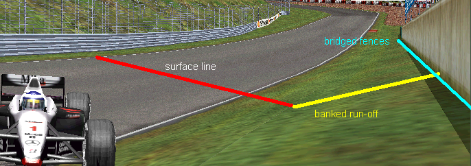
TRACK BORDERS In the beginning we need to specify which parts of the track are involved in this section of the editing. What we call run-off area is composed of two parts: the road side and the run-off area. the road side is a strip that runs along the track for a bunch of units, while the proper run-off area is the following space finishing with the fences. Commonly the roadside is used to map the border lines of the track and the textures immediately next to the road surface. Here is also where the kerbs will lay. The run-off is left to the gravel trap with sand or tarmac areas.Once modelled the track we can move on editing the run-off areas and walls. Opening again the track dialog box of the track sectors we can set the distance of the walls from the border line. The entries to edit are grouped in the ‘Bank’ frame, related to left and right. Valid values are from 0 to 255 units.
If many consecutive sectors have the same width, we can use the option ‘set all banks to…’ from the TRACK menu to save time, as shown in the previous chapter. This time we also need to select the starting sector and the final sector of the group and the side where to apply the change. The walls will always follow the radius of the sectors, but we can use an option that allows to straight the walls of a single sector or a group of sectors (curved or not). This operation is called wall bridging. Here is an example of how it works. Let’s consider the two curved sectors marked with the blue dot. They are still not bridged.
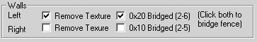
Opening the dialog box for both sectors and checking the opions like below we can straight the walls inside the turn, enlarging in this way the run-off area:
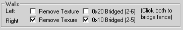
Of course we must use carefully this option because bridging in example the external sector we’ll cause a floating wall cutting the track:
A limitation of this feature is that the wall bridging works only if the total bridged length is at least of 3 units or more. Bridging sectors for an amount of 2 or 1 units will make the game crash to desktop. This issues is anyway avoidable running the game in debug mode. Let’s consider this portion of track: As explained previously, the width of the run-off area on the sector t0 is given by the option Track Config of the Track Tree. Usually the value in track config should match the value of the width entered for the sector t0 and the last sector of the track to be linear. Another important thing to know is that using the bridged fences in presence of relievant height may cause undersidered effect. Remembering that the bridging goes straight from the point A to B, if the area in the middle has a hump we'll se an unrealistic stretching of the run-off. At the same way if there is a depression we may see an unnatural banking with the car sinking on it.
PLACING KERBS Now we need to place some kerbs around the track. Usually they are placed at the internal side of the turns and at the exit of the them in the external side. In Gp3 Kerbs are divided in left and right kerb. For each side there are two profiles available: the Type A and the Type B to create different combinations. Each one of the profile is composed of two elements: the inside section that is the one immedialey next to the road side and the outside section which is the extention of the internal section andd each section can have it's own texture. Each profile is identified by a own code 0, 1, 2, 3. Here below are summatized the profiles: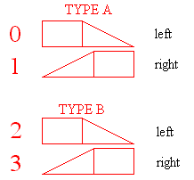
By default all the settings about the kerbs are contained in the sector t0 of the track. Here there are four commands 0xca 'Kerb profile' which define the profiles and eight texture mapping commands which define the mapped texture on each section. They provide the custom shapes and textures that will be used for the entire track by default unless we decide to change them somewhere else along the track.
It's good to know that the kerb profile commands work like a trigger. If we decide to change the shape of a kerb at a certain point by adding another 0xca command, from that point to the end of the track all the kerbs of that side and type will have the same shape. This means that after any variation we do, we need to be set the values back ny adding another profile command with the default values. So, first of all we must fit the profile of each one of the kerbs type to our project. Opening one by one the four kerb profile commands we'll enter the window where to change the parameter of that type of kerb:
Once choosen the profiles, we need to choose which texture we want to map on them. This operetion can be done whenever we want so will be discussed in the Texturing chapter. Now we can place the kerbs in the track. To add a kerb we need to open the dialog box of the desired track sectors and check the side (or both if needed…) where to apply it.
The third option (kerb selector) is needed to choose between the type A and the type B of the profiles so the type B is selected if the kerb selector is checked too. Whatever is the choosen type or side, if it is curved sector, the kerb will be applied to the entire length of it, while in case of straight sectors it covers only a part of its length. In this case or in case we need cover only a short interval of a sector, we need to use specific commands that allow to define the exact lenght we want to cover with kerbs. These commands are 0x8e 'LEFT KERB BEGIN LENGTH' and 0x8f 'RIGHT KERB BEGIN LENGTH' Let's do an example. In the image below we have applied a Type B kerb to three sectors for a total lenght of 25 units
What we want is instead a kerb covering only 18 units. In the starting sector (1) we'll place a 0x8e command. opening this command with a double click we'll see 3 arguments:
a1 is clearly unused a2 is the starting offet of the kerb area where zero is the point where the command has been placed. a3 is the lenght we want to cover with kerbs. with the above setup the result will be the following:
if we change the offset in a2 to 11 and the lenght in a3 to 7 we'll get the following result:
Notice how despite the three sectors are still checked we have a smaller kerb. If we want to change the shape of a kerb at half track and only for a couple of turns here is the sequence of command we need to insert to make the trick. Say we want to edit the Tipe B of the left side kerb
The default profile is set in t0 as explained before. From t0 to to t48 all the left kerb of Type B will have the same shape. In t49 we added another command with a different profile. From now on all the left kerb of Type B will have this new shape. In t80 we want to change again the shape. We set back the default profile but can be any other profile if needed, so we added another command. From the rest of the track left kerb of Type B will have this other shape.