

TRACK COMPONENTS A Gp3 track is composed of many parts. Every part has a name and a code to be identified when weĺll apply a command to it. Here is a scheme of the track:This is the list of identification labels and ID codes for each part: SCENARY RIBBONS L1: LEFT RIBBON 1 = áid. 18 R1: RIGHT RIBBON 1 = áid. 19 L2: LEFT RIBBON 2 = áid. 14 R2: RIGHT RIBBON 2 = áid. 20 L3: LEFT RIBBON 3 = áid. 13 R3: RIGHT RIBBON 3 = áid. 21 L4: LEFT RIBBON 4 = áid. 12 R4: RIGHT RIBBON 4 = áid. 22 L5: LEFT RIBBON 5 = áid. 11 R5: RIGHT RIBBON 5 = áid. 23 á ROADSIDE: RS: ROAD SURFACE = id. 10 FSL= FENCE SIDE LEFT= id. 40 FSR: FENCE SIDE RIGHT = áid. 39 RSL= ROAD SIDE LEFT= id. 38 RSR: ROAD SIDE RIGHT = áid. 37 á FENCING: LF: LEFT FENCE = id. 5 RF: RIGHT FENCE = id. 4 LFE: LEFT FENCE EXTENTION = id. 36 RFE: RIGHT FENCE EXTENTION = id. 35 If the width of the Road Side Right or Left is less than 11 units, they will be automatically changed into Right or Left Pitlane Verge: LPV: LEFT PITLANE VERGE = id. 9 RPV: RIGHT PITLANE VERGE = id. 8 KERBS: TYPE A LEFT KERB OUTSIDE = id. 3 TYPE A RIGHT KERB OUTSIDE = id. 2 TYPE A LEFT KERB INSIDE = id. 17 TYPE A RIGHT KERB INSIDE = id. 16 TYPE B LEFT KERB OUTSIDE = id. 26 TYPE B RIGHT KERB OUTSIDE = id. 25 TYPE B LEFT KERB INSIDE = id. 28 TYPE B RIGHT KERB INSIDE = id. 27 á SCENARY MODELING The scenary is the part of the editing that will take many commands, but it allows to make a very realistic work. The track scenary must be done on the track sectors and the pit scenary must be done on the pit sectors mainly for a matter of overlapping between objects and scenary parts. It's important to notice that when the car is on track the pitlane scenary will not be visible and viceversa, unles particular commands are used to limit this condition. The scenary consists of a certain number of arms between which the ribbons will connect. For a cheap reference it's like a tennis net connected between the two poles. Each side of the track has 5 ribbons, so it's like to have 5 tennis nets connected on top of eachother and theirs sides hanged to the same two poles. To build the scenary we must then add a couple of commands that defines what said before and since they work in couple, they must be placed always together at a given ofset. The command 0xaf (pair of swivel arms) places the arms and these are its arguments: a1= offset into sector a2= angle of the left arm (-R) a3= angle of the right arm (+R) It places one arm on each side of the track at the specified offset. The angles will tell for each side where the ribbons will fall by varying the inclination from the track direction. This command has two variants, in case we need to develop part of the scenary only in a single side while skipping the other side. They can be used in place of the 0xaf and are 0xc0 (left swivel arm) and 0xc1 (right swivel arm). Differently than the main variant these two bring only one angle aside the offset: a1= offset into sector a2= angle of the arm ((-R) left or (+R) right) This is the portion of a track:
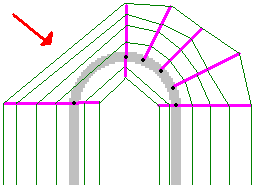
It is possible to see how the arms leave the track from its centre and with different inclinations. All the small areas are the ribbons, anchored on the arms at their distance so that the end of a ribbon is always the start of the next one. To decide the angles of these arms we can consider the picture below:
Comparing the two images it's clear how the angles are defined by power of 2 values. While + or - 16384 will create and perfectly perpendicular arm to the track, any other value will produce an certain inclination. Obvously extreme values tending to zero or 32768 will make the arms fall inside the the track with glitchy beam effects. So it's good use to make the fall outside the fencing. This will not interfer with the placing of the ribbons. To understand where and how to place scenary commands letĺs see the next two pictures. We can see that the ribbons can go from an arm to another (see the red arrow) almost in a straight way. So we need to place arms to model the desired scenary figure, be it a hill or a natural stand and so onů:
As we can see, in the second picture we added an additional arm on the left side of the track (0xc0 + 0xee) in order to define better that portion of scenary which otherwise would have been rougly defined. After having seen what the Ĺarmsĺ are and how they work, letĺs see what thereĺs between them. This is the command that define how the ribbons go from an arm to another. It is the 0xee Command (scenary structutre) and will lead to a table like the one below by double clicking it.
This is the upper part of the table. In Gp3 there are 10 ribbons, 5 on the right side (R1, R2, R3, R4, R5) and 5 on the left side (L1, L2, L3, L4, L5). To place a ribbon as we can see, we must define two parameters: the distance from the centre of the track (DFC,) and the height from the ground (Z). DFC will have negative values for the left side and positive values for the right side. Itĺs important to notice that the first ribbons (R1 and L1) still start from the centre of the track, though being indicated to start from the end of the fence width in the table. From a couple of commands (arms + structure) to another we must say the program how these ribbons are placed. L1 and R1 are the ones which are attached to the track, so they should be always activated in most of the scenaries. The rest of the job is up to the needs of the author. á In the lower part of the table, we have the heights of the track and the placement of the ribbons, better said which ribbons are activated along the track.
The colors indicate the ribbons, from the yellow one on the top (L5) to the grey one on the bottom (R5), (red one is R1 and so onů). Also the blue line refers to the heights of the pitlane. This line can be tricky because it starts from the starting line of the track, while its real start should be somewhere on the right side of the chart of course, there is the end of the track. The red marked sector is the track sector where we placed the current command and the numbers are the index numbers of the sectors. As shown, we can turn on only the ribbons we need in a certain point. The commands to enable/disable these ribbons are 0xea (switch ribbon on) and 0xeb (switch ribbon off) Their arguments are the same and regard the offset in which the ribbon will turn on/off starting from where the command has been placed and the code of the ribbon: a1= offset a2= code of the ribbon á These commands allow to enable/disable 1 or more ribbons simultaneously. This is list of codes usable in these commands: 1 ribbon L5 128 ribbon R5 2 ribbon L4 64 ribbon R4 4 ribbon L3 32 ribbon R3 8 ribbon L2 16 ribbon R2 256 ribbon L1 512 ribbon R1 These commands accept cumulative values, so if a2 = 18, weĺll turn on/off the ribbons R2 and L4 (16 + 2) and so on... With a2 = 752 weĺll turn on/off all the right ribbons and with a2 = 271 weĺll turn on/off all the left ribbons. Itĺs important to remember that all the unused ribbons must be turned off to avoid flashing effects. Sometimes, we may notice some ribbons or other parts of the track shifting and moving in an abnormal way. This may happen between two couple of scenary commands in the case of tight hairpins and in general curved sectors. In this cases we can use specific commands to stabilize the structure. Using 0xd0 (stabilize texture) we can stabilize the main parts of the track like road and fences: a1= offset a2= shifting texture a3= flashing texture á In a2 and a3 we must set one code or the sum of more codes listed below: á Code Description Code Description 1 ribbon R3 2 ribbon R4 4 ribbon R5 8 missing due to overlap? 16 right fence 32 left fence and right fence extension(!) 64 left fence extension 128 right verge 256 left verge 512 ámissing due to overlap? 1024 missing due to overlap? 2048 áribbon L5 and ribbon L1 (!) 4096 ribbon L4 and ribbon R1 (!) 8192 áribbon L3 16384 áribbon L2 32768 áribbon R2 -1 road surface á The commands that allow to stabilize the scenary are 0xba (Insert Dummy Scenery Arm Pairs), 0xc2 (Insert Dummy Scenery Arms Left) and 0xc3 (Insert Dummy Scenery Arms Right). Clearly, the main one will act on both side of the track at the same time, while the other two variants will take care only of one side, ignoring the other. a1= Offset into sector a2= horizontal interval: 0, 1, 2, 3, 4 etc a3= vertical interval: 0, 1, 2, 3, 4 etc Another command of the series allows to specify which ribbon to stabilize: 0xc4 (Insert Dummy Scenery Arms Specified). a1= Offset into sector a2= horizontal interval: 0, 1, 2, 3, 4 etc a3= vertical interval: 0, 1, 2, 3, 4 etc a4= specify wich ribbon Setting a2 with any value, weĺll create some fictive arms between two couples of scenary commands, so the ribbons will be rounded and smoothed in accordance to the number of the fictive arms added. Clearly shorter the number (but greater than zero), smoother will be the correction. In example, on a curved sector of 16 units lenght carrying the couple of scenary commands at the beginning, if we add a the 0xba command with a2 = 1 and a3 = 1, weĺll create a fictive arm every 1 unit and so on. Setting a2 = 0 and a3 = 0, weĺll disable this option and there will be no longer fictive arms along the sector. This commands work like a threashold, so it will take effect from the sector it is placed til the end or til another command of the same kind changes its status. So, to save commands, we can place a 0xba command in sector t0 wich will affect the whole scenary from the start to the end unless others are added later. In case of the 0xc4 command, to choose the specific ribbon we can refer to the previous table with the codes of the ribbons. When we build a scenary, we need to notice that we can add by default up to 128 scenary structure commands between track and pit scenary. So we can consult the table of the command stats to see how many commands we added since the beginning. In latest versions of GpXPatch this number has been increased, making this value no more relievant, though, the track editor may still refer to factory settings due to the earlier releasing era. á